This NX tutorial will teach how to design parametrized bulkheads, from a simple hull. The hull file must have the main dimensions defined in its expressions tool and the model used can be downloaded from the link:
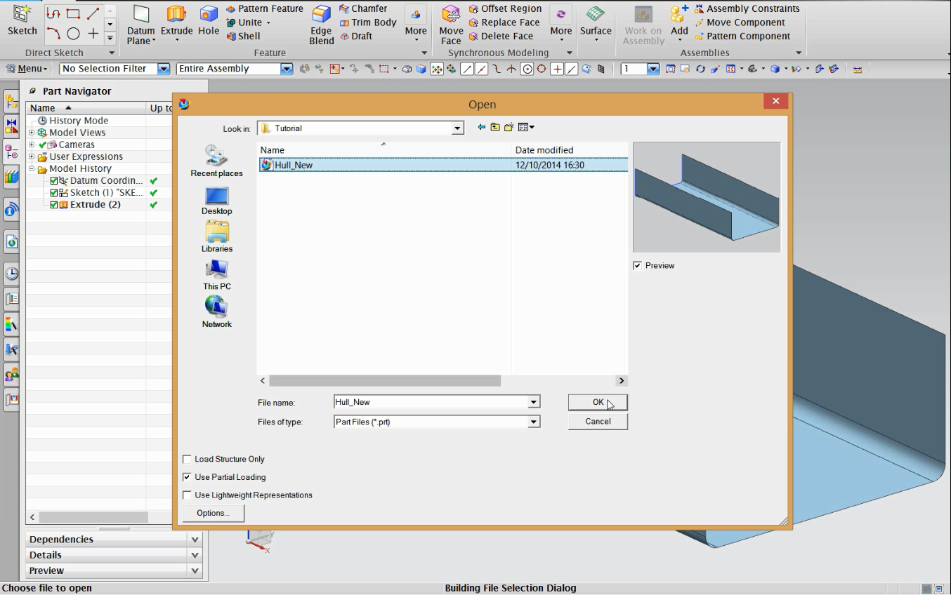
1-Open the Hull_New file.
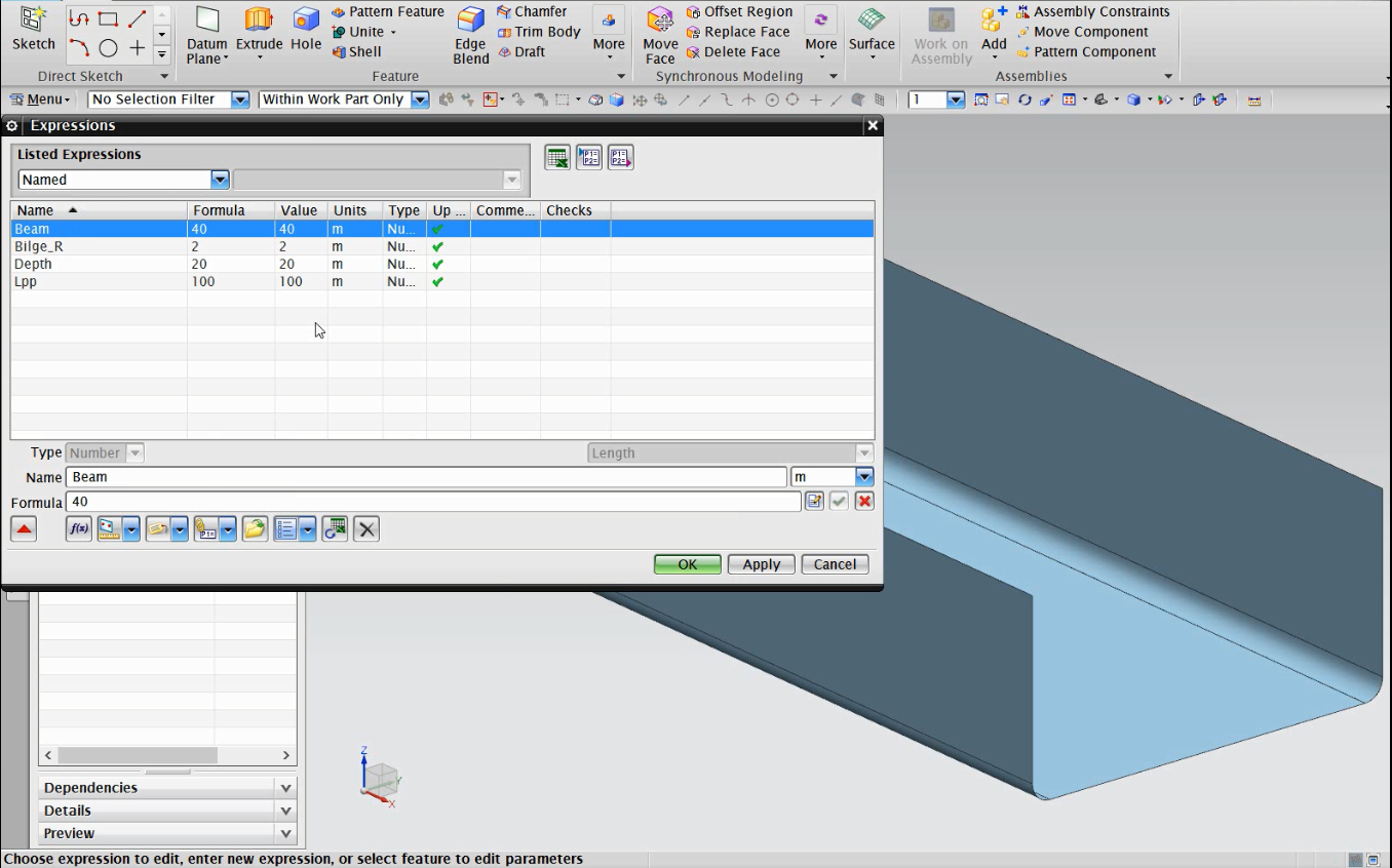
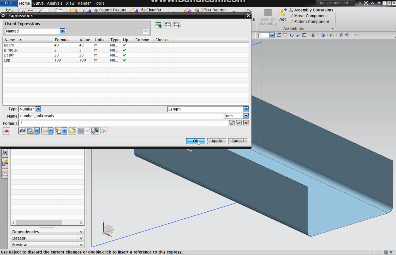
2-The file already contains expressions with the hull main dimensions.(ctrl+e to open).
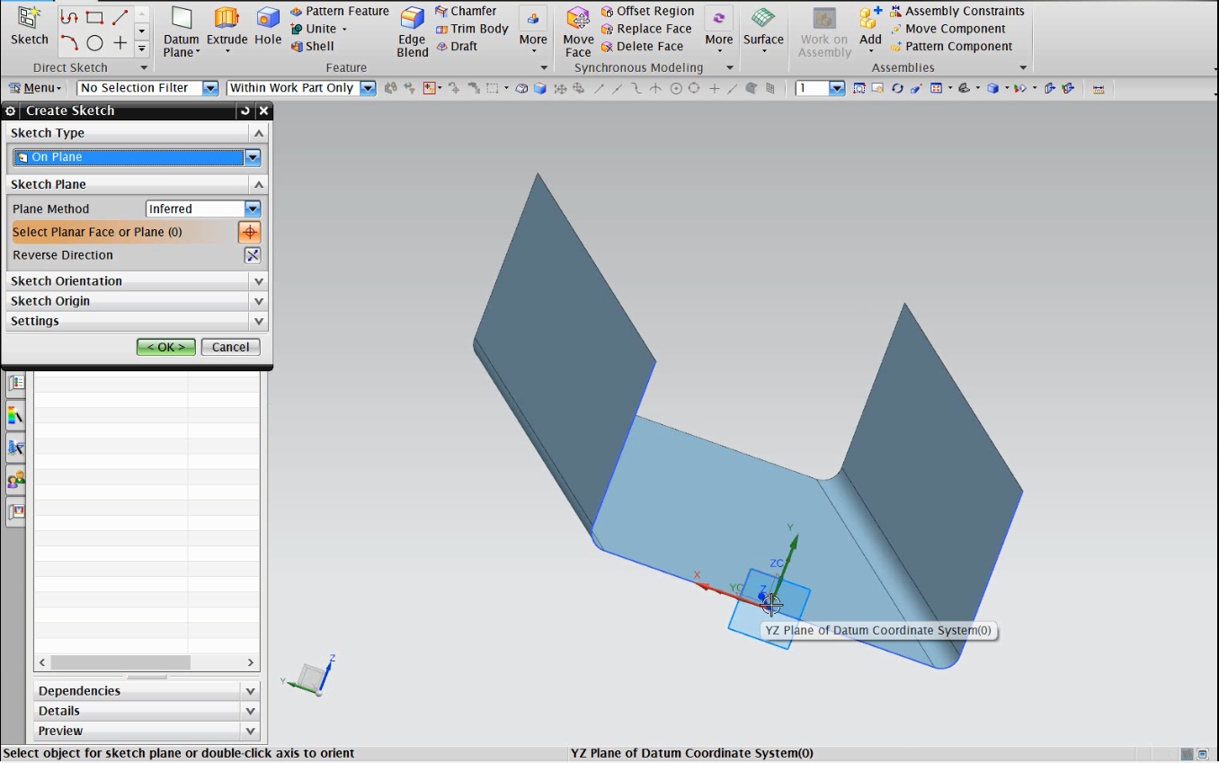
3-Create a sketch on the XZ plane at the model origin.
4-Draw a rectangle bigger than the mid-section of the hull. (For example, centered in the origin with 3xDepth of height and 2xBeam of length, this will guarantee that the plane is always bigger than the ship section, even if the expressions values are changed.)
5-Use rapid dimension to set the rectangle parameters. Use make symmetric to center it at the origin.
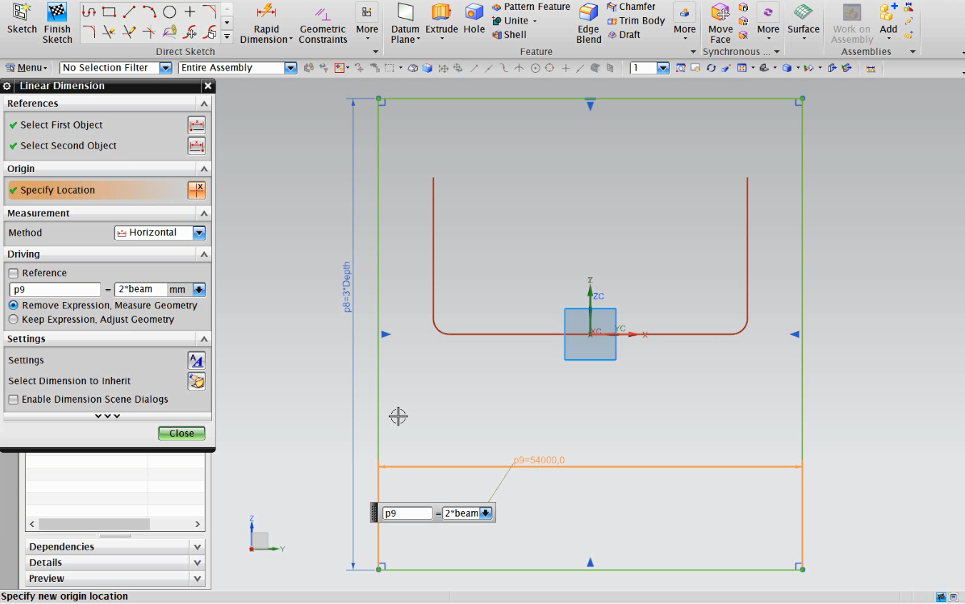
6-Finish the sketch.
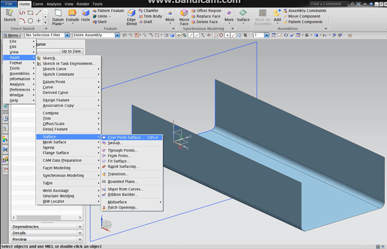
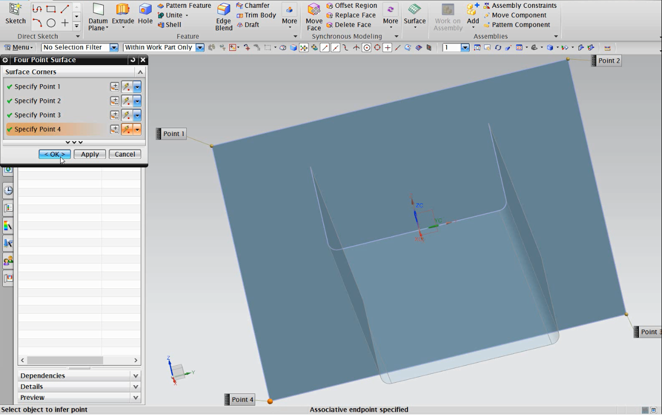
7-Use ‘four point surface’ to create a surface. Remember to set the points in order.
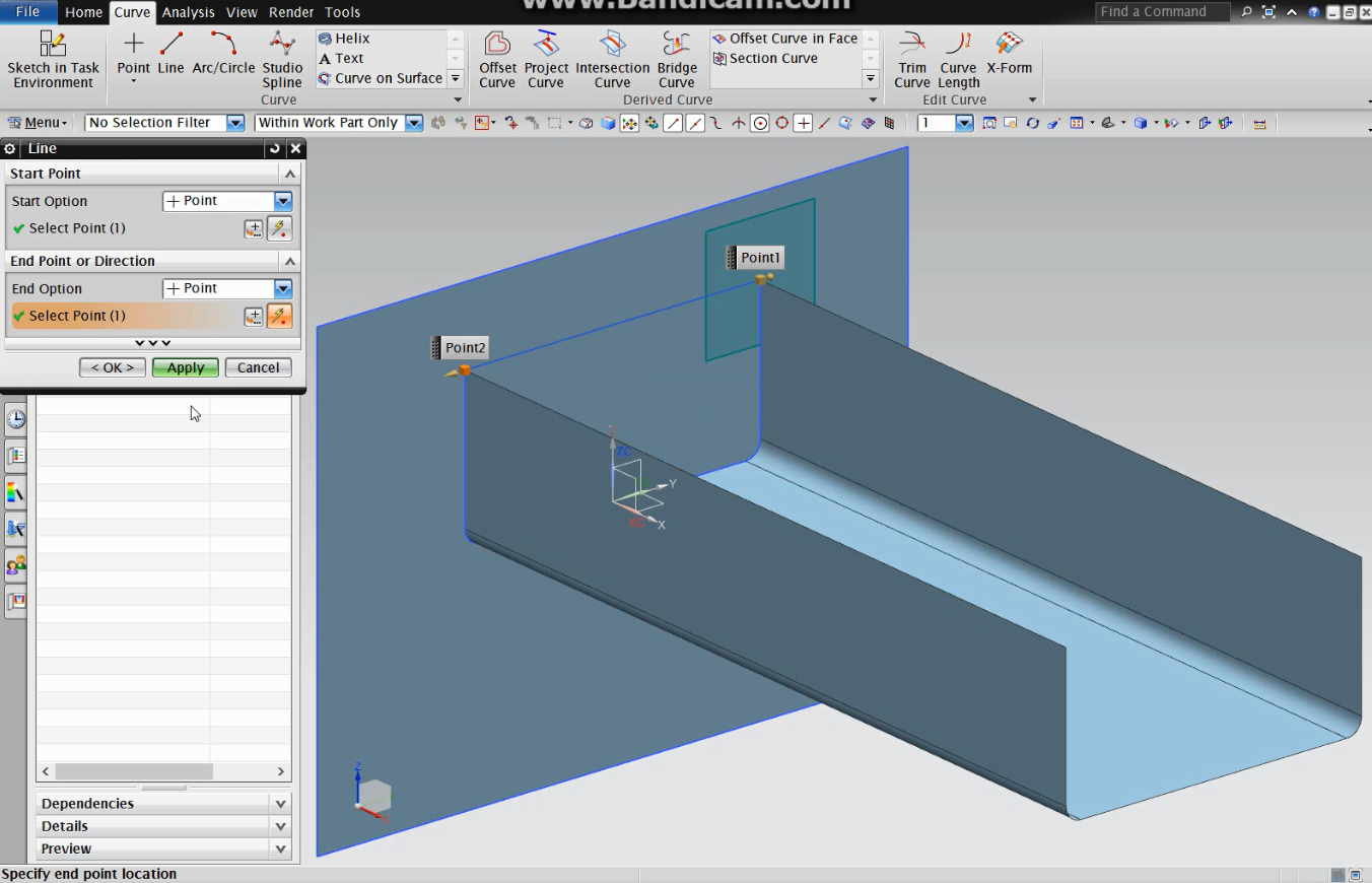
8-Go to ‘Curve’ and create a line as shown:
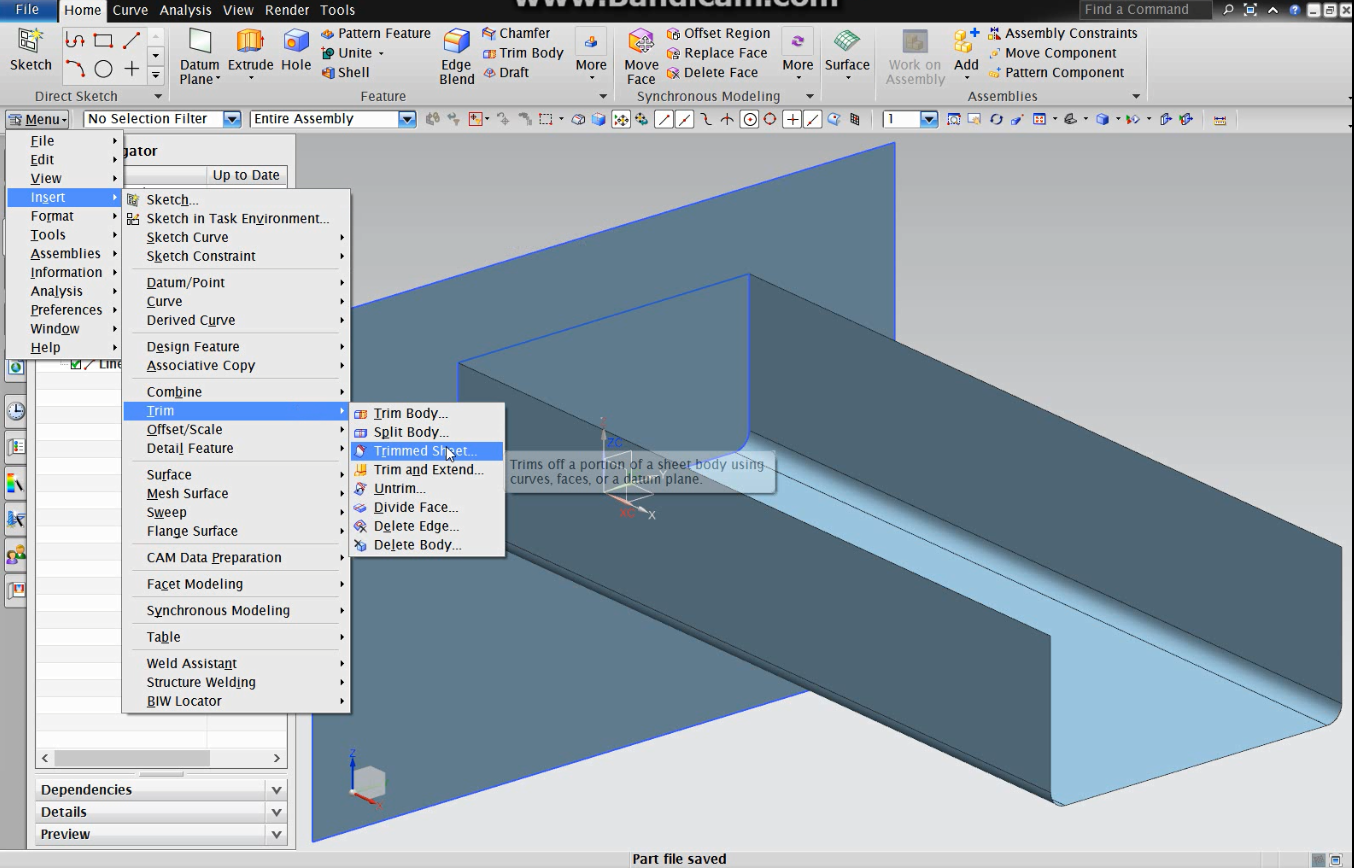
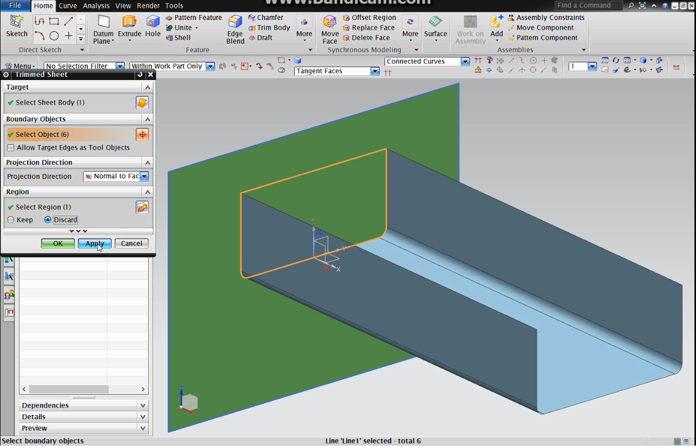
9-Now you create a closed curve, which will be used to cut the surface. Using ‘trimmed sheet’, select the surface created and then the hull sketch and the line just draw.
10-Open the expressions menu (ctrl+e) and create a new expression that will set the number of bulkheads.
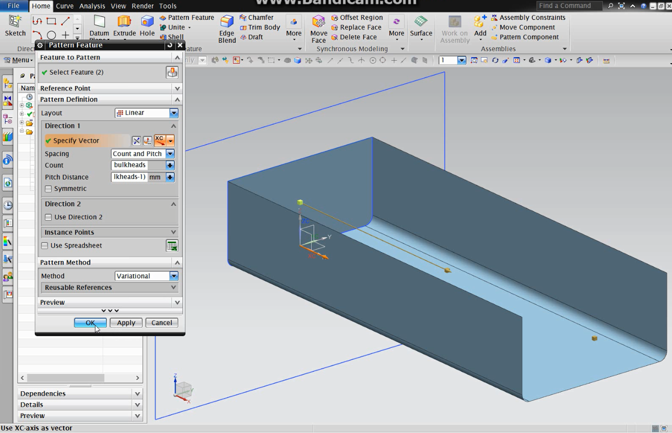
11-Select ‘pattern feature’. Be sure to select as feature the surface and the trimmed sheet.
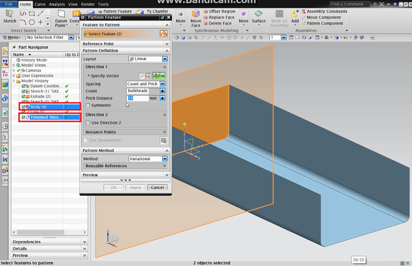
12-The Layout is linear, the vector is XC, the spacing is count and pitch, the count number_bulkheads and the pitch distance is lpp/(number_bulkheads-1). This will create an parametric design, where we can change any expressions value, changing the hull design, and the bulkheads will adapt.