
by Thiago Gabriel Monteiro – MSc Student in Ship Design / Høgskolen i Ålesund
(thiagogabrielm@gmail.com ), v1, Oct 2014.
Read the report here
[toc]
1 – Introduction
This tutorial aims to introduce a very simple way of doing a parametric vessel modelling at Siemens NX. This parameterization will allow a modular approach at the vessel design. So, it will be possible, besides changing the dimensions, to exchange different parts in order create the final concept.
In this tutorial will be explained how to create an assembly file which will contain all the parameters used during the model construction. These parameters will be loaded in each modeled part, so they will be constructed based in the main dimensions of the final design. When all parts are modeled and assembled together, it will be possible to change the dimensions of the entire model only by changing the parameters stated at the main assembly. The parts at the main assembly can be exchanged in order to fulfill different needs.
2 – Videos
2.1 – Assembly File & Middle Section
2.2 – Stern Section
2.3 – Bow Section
2.4 – Super Structure Block & Motor Block
2.5 – Assembling Model
3 – Assembly File
The first step at the modeling process consists of creating a new assembly file in NX. This assembly file will be used to put together the design parts at the end of the modeling process and to store the variables containing the main dimensions of the final model.
Once the assembly file was created, it is possible to open the Expressions window by two means. The first and fastest one is using the shortcut CRTL + E. The second option is clicking the menu Tools, and then the Expressions buttons, as highlighted in the Figure 1.
In the Expression window, it is possible to create variables to define the main dimensions of the vessel. It is important to correctly define the units used to define the variables. At the field Name, it is possible to define the variable’s name. At the field Formula, it is possible to add a mathematical expression or simply a value, which will be attributed to the variable.
With all the needed variables defined, the assembly file can be saved and the modeling of all the vessel’s parts can begin.
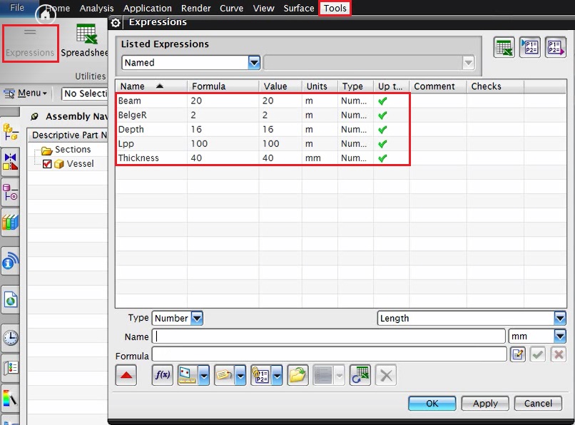
Figure 1 – Expressions window
4 – Modeling a simple hull
In this modeling, the vessel’s hull will be dived in three parts: the stern, the middle section and the bow. This approach aims to create a design which will be modular, being able easy change the model by exchanging its parts.
4.1 – Middle Section
The first part to be modeled will be the middle section. Once a new part file is created, the expressions window should be opened. At the expressions window, the “Create Multiple Interpart Expressions” (Figure 2) option should be selected. This option allows the sharing of expressions through different files, and will be very important in order to parameterize the model.
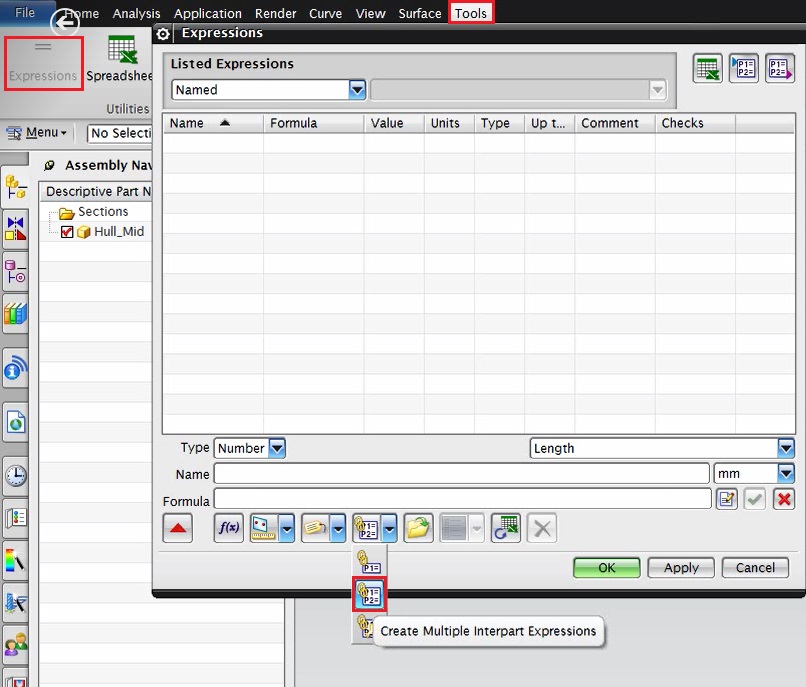
Figure 2 – Creating Multiple Interpart Expressions
A new window wills pop-up. At this window, the assembly file created previously should be loaded and selected to share its expressions with the hull’s middle section part. After loading the assembly file, the expression which will be shared should be selected at the Source Expressions sub window and the add button should be pressed to include the selected expression from the original file to the recently created one. All this process is shown, step by step, at Figure 3.
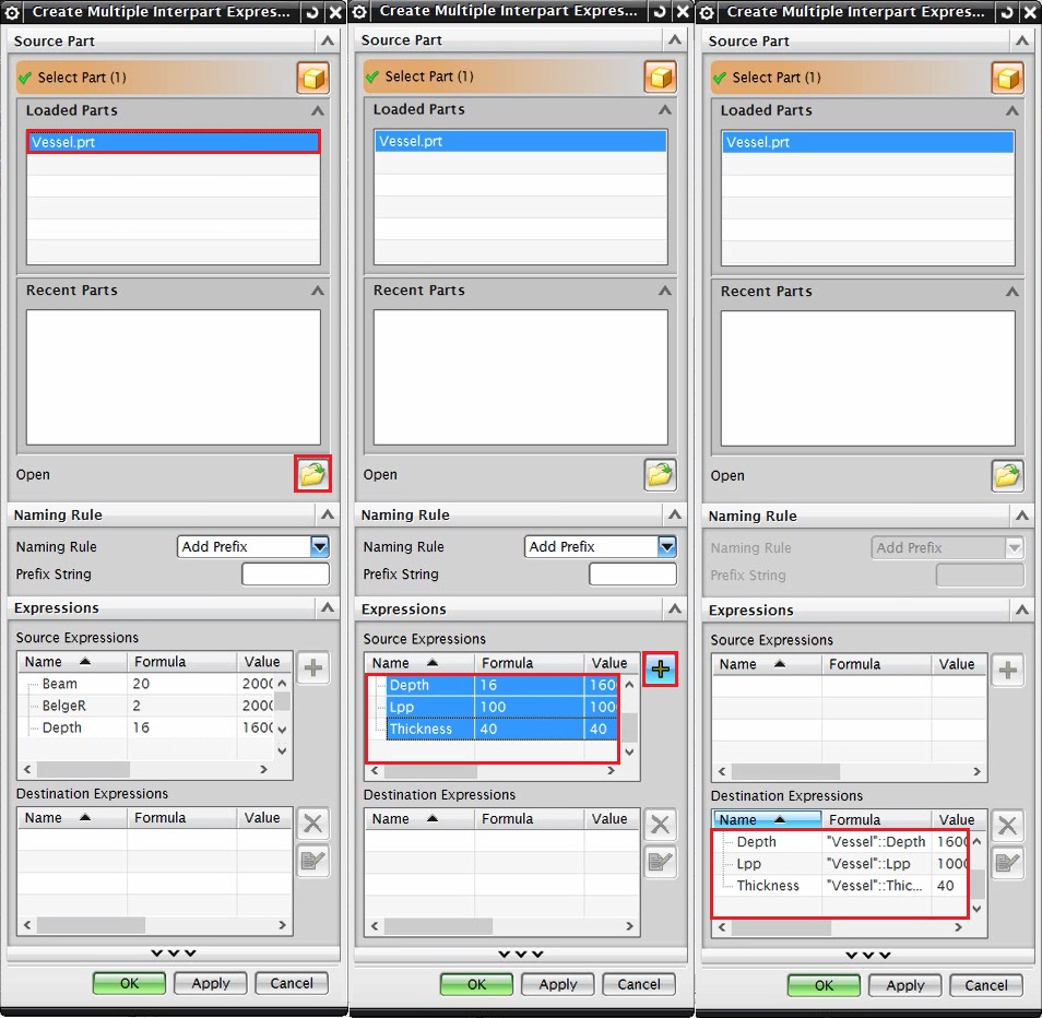
Figure 3 – Creating Multiple Interpart Expressions Process
After added, the variables can be seen at the at the expressions window. It is possible to verify that the formula field of each variable contains the expression “Vessel”, which indicates the original file from where the expression is being shared. Once the variables’ values are changed in the original file, they will also be changed at the files which share the same variables.
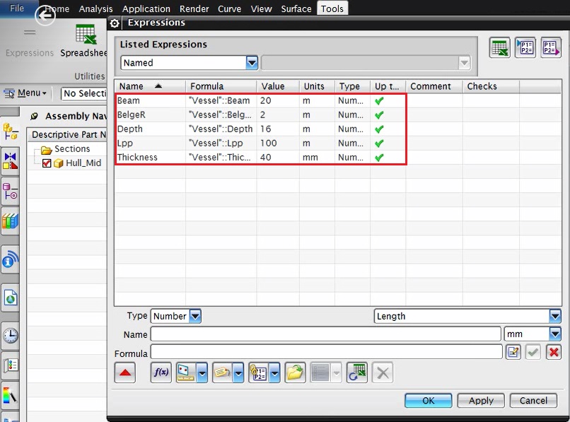
Figure 4 – Imported Expressions List – Middle Section
After importing the variables list, it is time to start the modeling process. The vessel’s middle section cross section can be seen at the Figure 5. The important thing here is the parameterization. Each dimension used in the sketch refers to a variable previously defined. In order to use an expression already defined to specify the value of a sketch’s dimension, it is necessary to type the variable’s name at the dimension box from the rapid dimension tool.
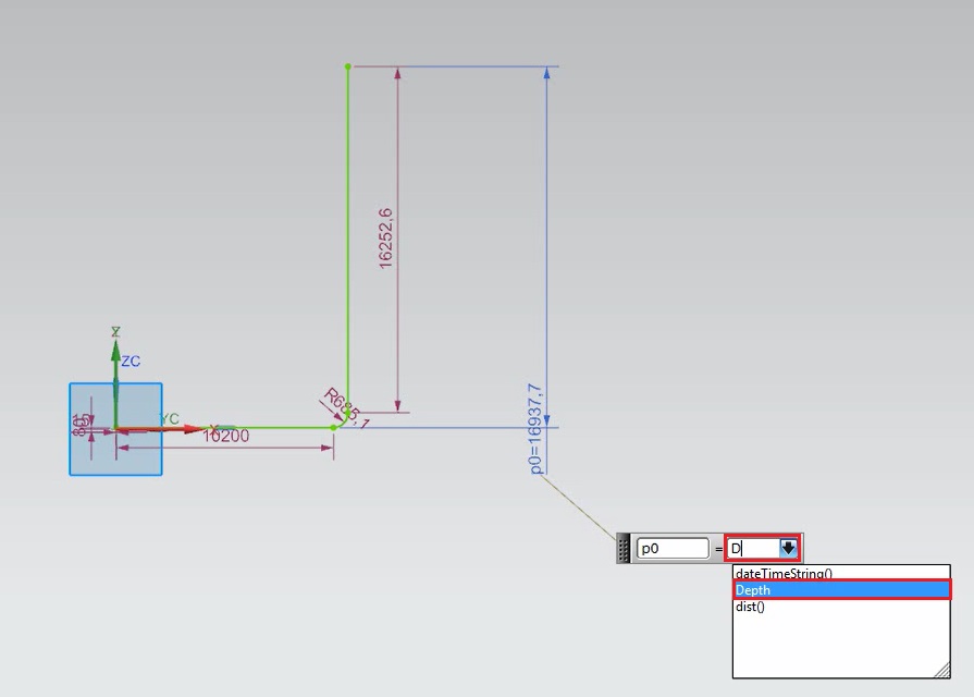
Figure 5 – Dimensions Parameterization
After all the dimensions of the sketch are parameterized, the cross section will look like the one presented at Figure 6. To make the sketch process easier, it is possible to use the Mirror commando in order to avoid drawing the same section two times
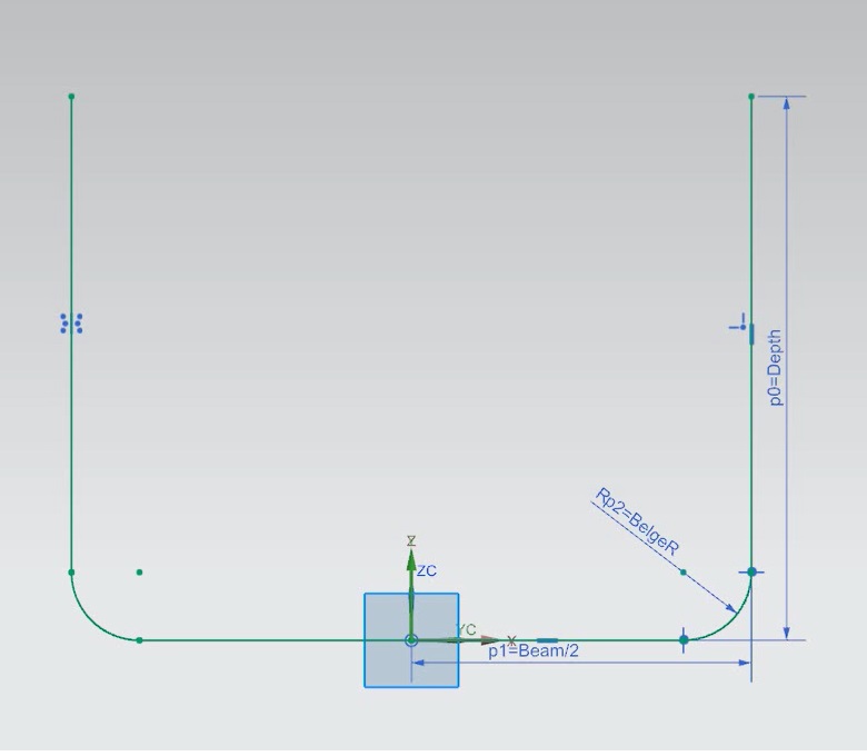
Figure 6 – Parameterized Middle Cross Section
In order to create the middle section of the hull, it will be used the Extrude command. The section to extrude should be the one sketched before. The parameterization will take place at the distance field, which defines the size that the cross section will be extruded. Here, it was selected a percentage of the total length of the hull to define the middle section, namely 50%. This procedure can be seen at Figure 7.
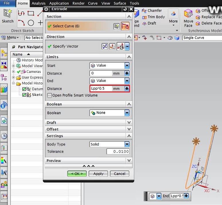
Figure 7 – Middle Section Extrude Process
The extruded sheet body can be seen at Figure 8.
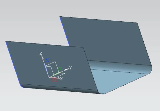
Figure 8 – Extruded Middle Cross Section
Depending on the application of the model, it can be interesting (or even necessary) to have a solid body instead of a sheet body. To do so, it is enough to use the command Thicken, in order to add thickness at the selected sheet body.
The Thicken command will also be parameterized with one of the previously created variable. It is important to verify if the thickness is going to be added inward or outward. It can be controlled by using the button Reverse Direction. In this case, the selected direction (in order to keep the dimensions already parameterized whit no increase) is the inward direction. This process can be seen at Figure 9. After that the modeling is finished and the design can be saved.

Figure 9 – Thicken Process
4.2 – Stern Section
The first thing to do at the beginning of the stern modeling is to import the variables list created at the assembly file. All the procedure used to link the variables between the two files can be followed at Figure 2 and Figure 3. The final list can be seen at Figure 10.
The modeling will start by sketching the same cross section used at the middle section part. This section will be the interface linking both sections at the final assembly. The final sketch can be seen, again, at Figure 11.
Figure 10 – Imported Expressions List – Stern Section
Figure 11 – Stern Interface Section
Since the stern section usually has a more complex shape, it will be needed another working plan to sketch its end section. To do so, it will be created a Datum Plane, distant 20 percent of the hull’s length from the interface section. At Figure 12, it is possible to see the datum plane creation procedure.
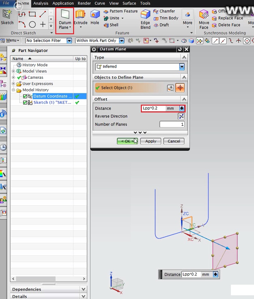
Figure 12 – Datum Plane Creation Procedure
At a new sketch plane, created at the previously generated datum plane, the end section should be drawn and parameterized. At Figure 13, it is possible to verify the parameterization done. Again, it is recommended to use the Mirror command to make the sketching process easier.
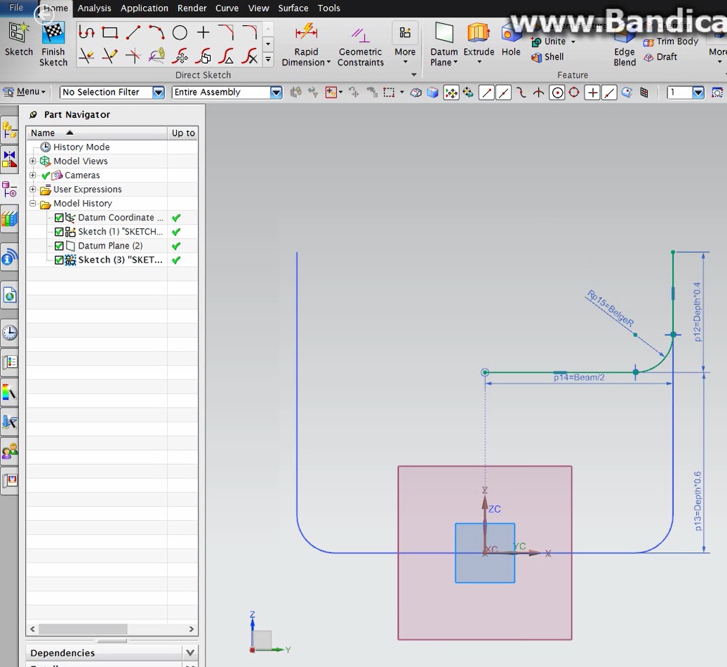
Figure 13 – Stern’s End Section Sketching
Once the two sections are sketched, it is time to generate the surface through them. To do so, it will be used the surface generating command Through Curves. To correctly use the command, it is necessary to create one different set of curves for each section. After selecting the curves composing one section, the button Add New Set should be pressed, in order to add these curves to the set list. Once the two sets are added, the surface will be automatically generated. The generating process can be followed at Figure 14 and the final result can be seen at Figure 15.
Figure 14 – Stern Surface Generating Process

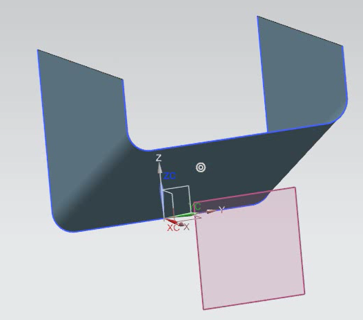
Figure 15 – Stern Sheet Body
After the sheet body is created, it is possible to apply the Thicken command to add thickness to the surface and create a solid body. The stern section was thickened using the same parameterization applied at the middle section.
To close the end section, it will be added a sketch line, which will be used to generate a new surface (Figure 16).
The closing surface will be created using the Through Curve command. The first set of curves should be the just created sketch line. The second set of curves should be the inner contour of the end section. The process can be seen at Figure 17.
After the sheet body is created, the Thicken command is used as before, to add thickness to the body.
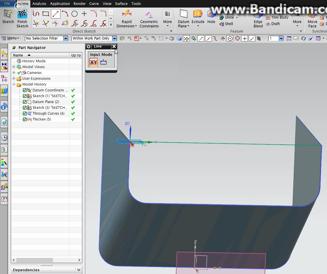
Figure 16 – Sketch to Close the End Section
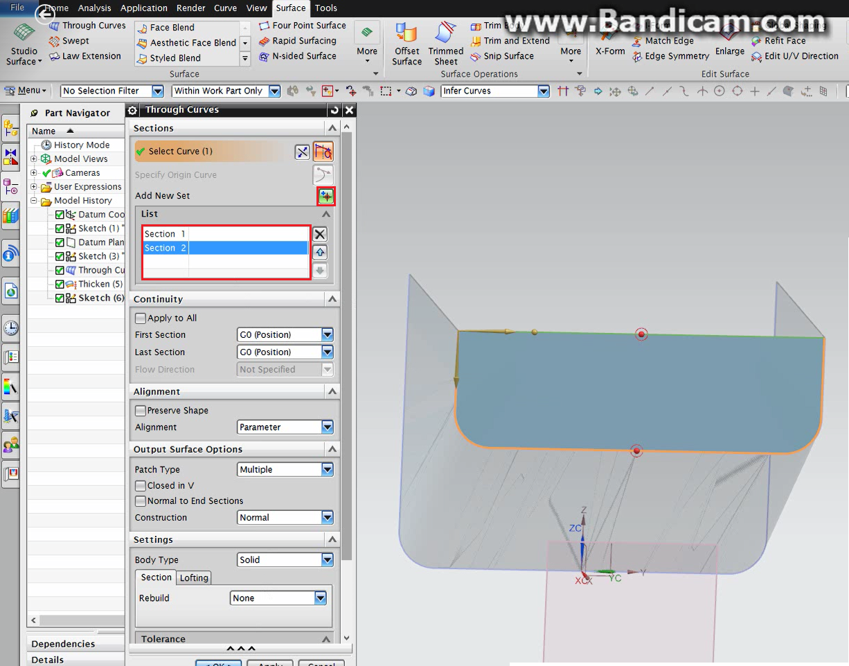
Figure 17 – Closing the End Section
The finalized stern section can be seen at Figure 18.
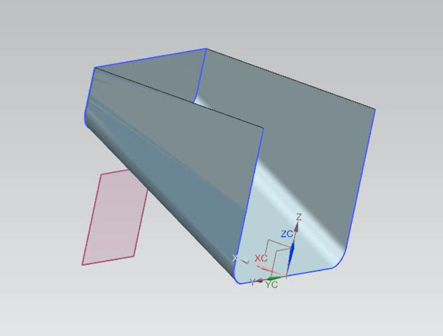
Figure 18 – Finalized Stern Section
4.3 – Bow Section
The first thing to do at the beginning of the bow modeling is to import the variables list created at the assembly file. All the procedure used to link the variables between the two files can be followed at Figure 2 and Figure 3. The final list can be seen at Figure 19.
The modeling will start by sketching the same cross section used at the middle section part. This section will be the interface linking both sections at the final assembly. The final sketch can be seen, again, at Figure 20.
Figure 19 – Imported Expressions List – Bow Section
Figure 20 – Bow Interface Section
The bow section is going to be simpler then the stern one. It will be generated by extruding the interface cross section. The extrude command will be parameterized using 30 percent of the length variable. So, adding the sizes of the three sections, the vessel’s hull will have 100 percent of the length variable. The extrude process is shown at Figure 21.
After the sheet body is created, it is possible to apply the Thicken command to add thickness to the surface and create a solid body. The now section was thickened using the same parameterization applied at the middle and stern sections.
The closing surface will be created using the Through Curve command, dividing the inner contour of the first section in two sets of curves. The process can be seen at Figure 22.
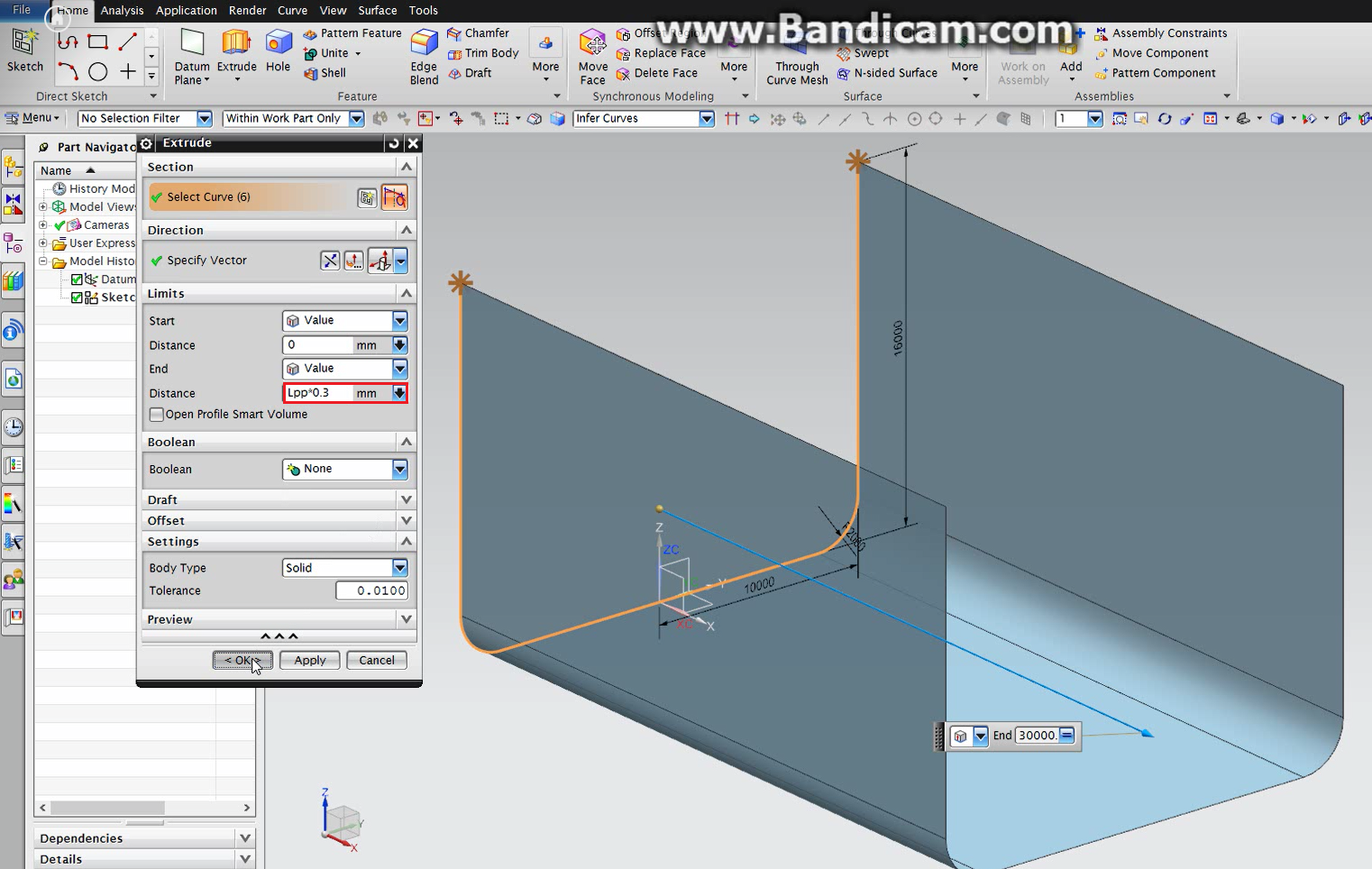
Figure 21 – Bow Extrude Process

Figure 22 – Closing the First Section
After the sheet body is created, the Thicken command is used as before, to add thickness to the body.
The finalized bow section can be seen at Figure 23.
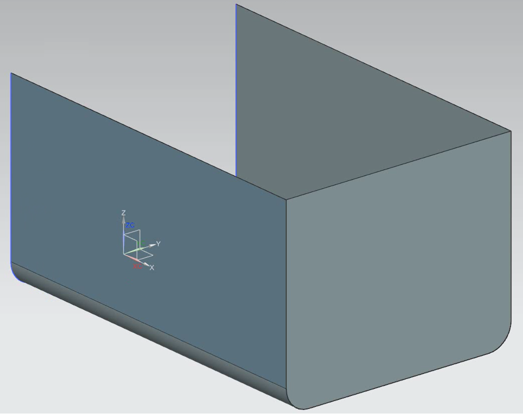
Figure 23 – Finalized Bow Section
5 – Modules Design Examples
At this chapter will be presented, as examples of modules constructions, the design of a simple superstructure block and a simple motor block. This modules will be integrated with the final design and will also be exchangeable and with variable dimensions.
5.1 – Superstructure
The superstructure will be constructed as a solid block, which will be positioned at the top of the vessel’s hull during the assembling.
To star the modeling, the first thing to do should be the importing of the variables defined at the assembly file. All the procedure used to link the variables between the two files can be followed at Figure 2 and Figure 3.
After the importation is done, it is time to begin the modeling procedure. The first step consists of a rectangular sketch at the horizontal plane (x-y). The sketch parameterization can be seen at Figure 24.
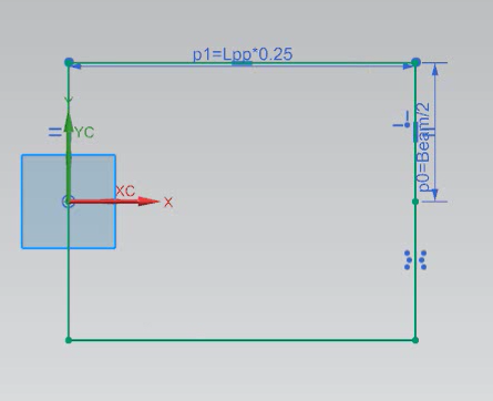
Figure 24 – Superstructure Sketch Parameterization
The superstructure block will be generated by extruding the just created sketch. The extrude command will be parameterized using 80 percent of the depth variable. The extrude process is shown at Figure 25.
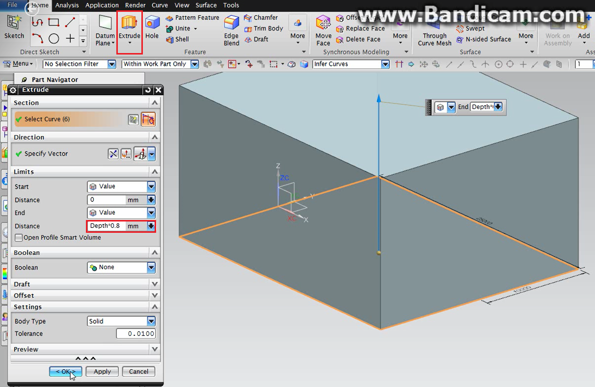
Figure 25 – Superstructure Extrude Process
In order to add a small detail at the superstructure block, it will be used the command Chamfer. It will be asymmetric and applied at the edge highlighted at Figure 26, being parameterized with 40 percent of the depth variable at the vertical direction and 16 percent at the horizontal direction.
The final piece can be seen at Figure 27.
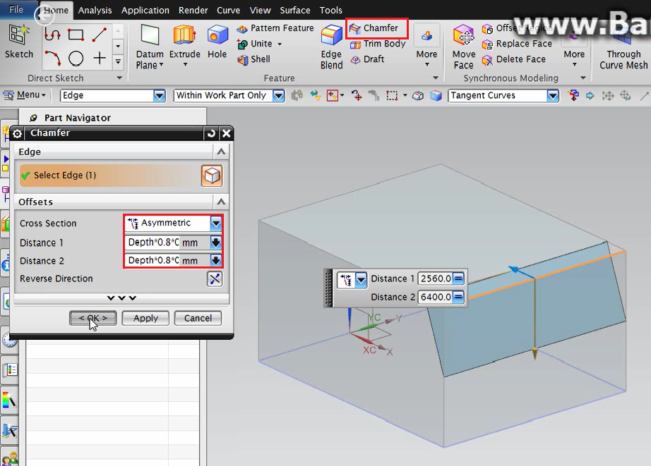
Figure 26 – Superstructure Detailing

Figure 27 – Final Superstructure Module
5.2 – Motor Block
The motor block will be constructed as a solid block, which will be positioned inside the vessel’s hull bow section during the assembling.
To star the modeling, the first thing to do should be the importing of the variables defined at the assembly file. All the procedure used to link the variables between the two files can be followed at Figure 2 and Figure 3.
After the importation is done, it is time to begin the modeling procedure. The first step consists of a sketch of the vessel’s cross section. Since this body will be inside the hull, it is important to discount the thickness variable from each dimension. The sketch parameterization can be seen at Figure 28.
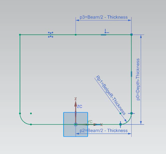
Figure 28 – Motor Block Sketch Parameterization
The superstructure block will be generated by extruding the just created sketch. The extrude command will be parameterized using 30 percent of the length variable minus the thickness variable. The extrude process is shown at Figure 29.
The final design can be seen at Figure 30.
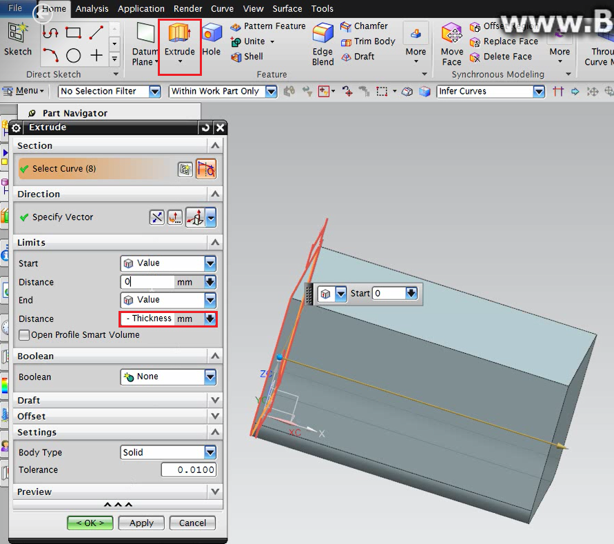
Figure 29 – Motor Block Extrude Process
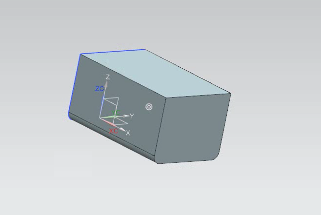
Figure 30 – Final Motor Block
6 – Assembling
In order to star the assembling process, the first step should be opening the assembly file. At the assembly file (which is empty right now, besides the previously created expressions) it is necessary to load the part which will compound the final model. For this, the command Add New Part should be used. The first part to be loaded is the stern section. In the field placement, the positioning method should be Absolute Origin. The load process can be seen at Figure 31.
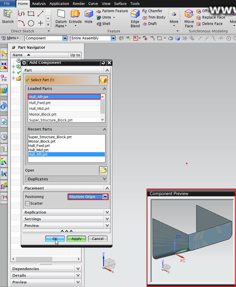
Figure 31 – Stern Section Load
Because the way the part was modeled, it needs to be rotated by 180 degrees, in order to be oriented at the positive X-axis direction. It can be done using the Move command. The process can be seen at Figure 32.
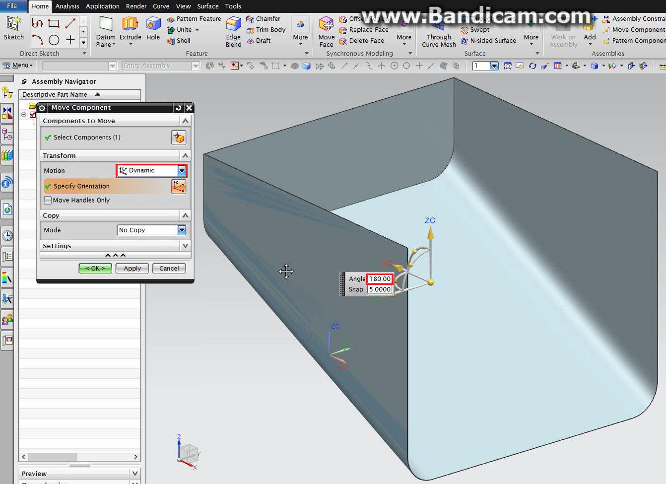
Figure 32 – Stern Section Positioning
The next step is loading the middle section. Now, the placement field should contain the By Constraints method. This will allow the right positioning of the part in relation to the part previously loaded. The process can be seen at Figure 33.
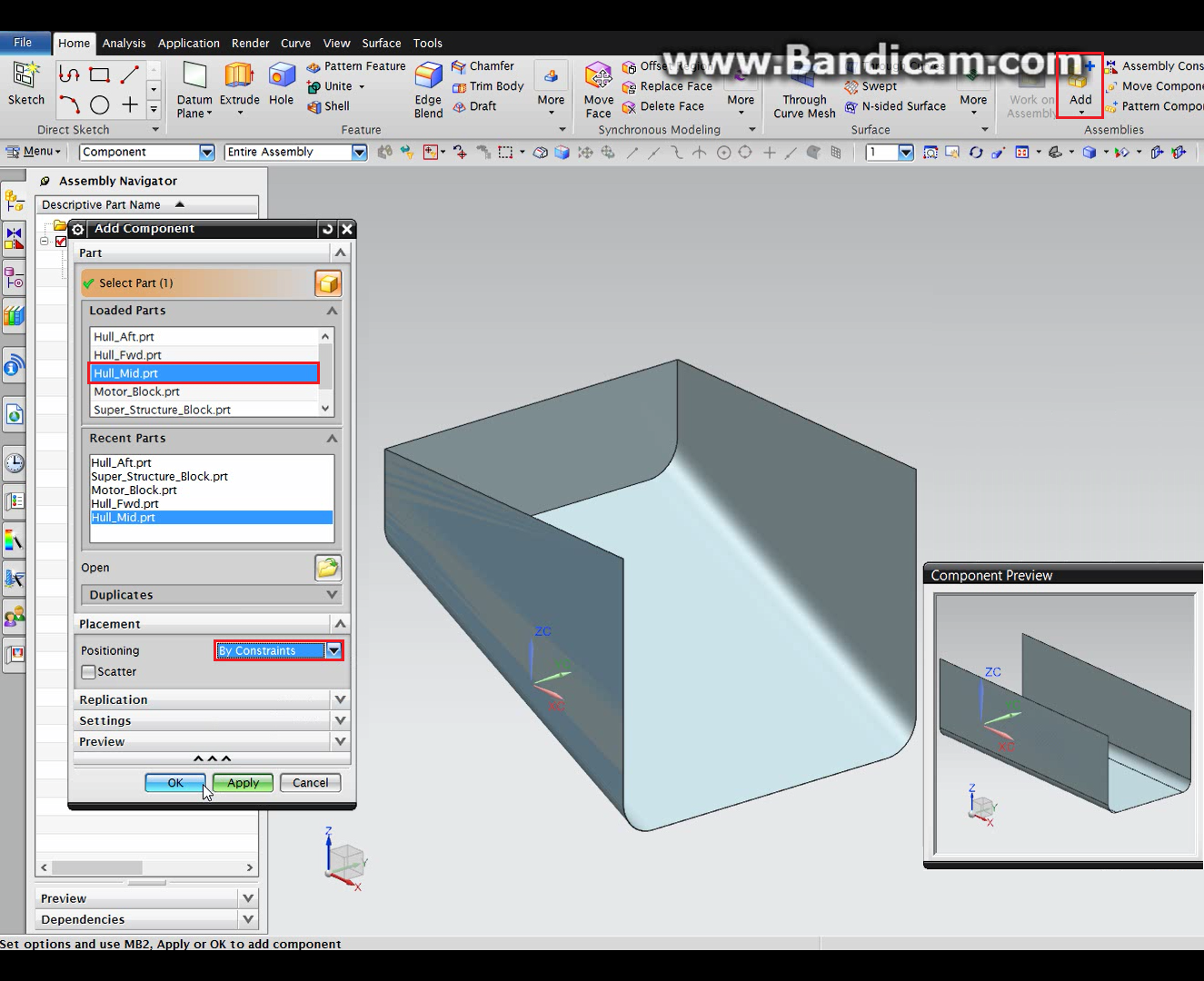
Figure 33 – Middle Section Load
The constraint type applied will be Touch Align. In the orientation field, the Touch option should be selected. The touching face edges (the interface sections) should be selected in both of the part, at the component preview window for the middle section and at NX main window for the stern section. It is also important take care about the order that the faces are selected. The face to be placed should be selected first. In this case, the middle section face should be selected before the stern one. The process can be seen at Figure 34. The positioning result can be seen at Figure 35.
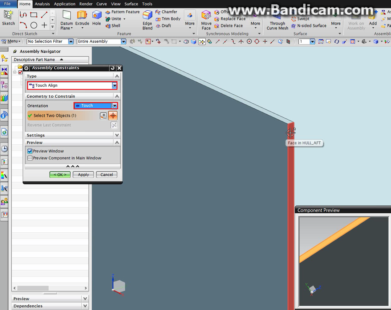
Figure 34 – Middle Section Positioning
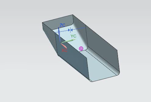
Figure 35 – Stern and Middle Sections Positioned
The next step is loading the bow section. The placement field should contain the By Constraints method. This will allow the right positioning of the part in relation to the parts previously loaded. The process can be seen at Figure 36.
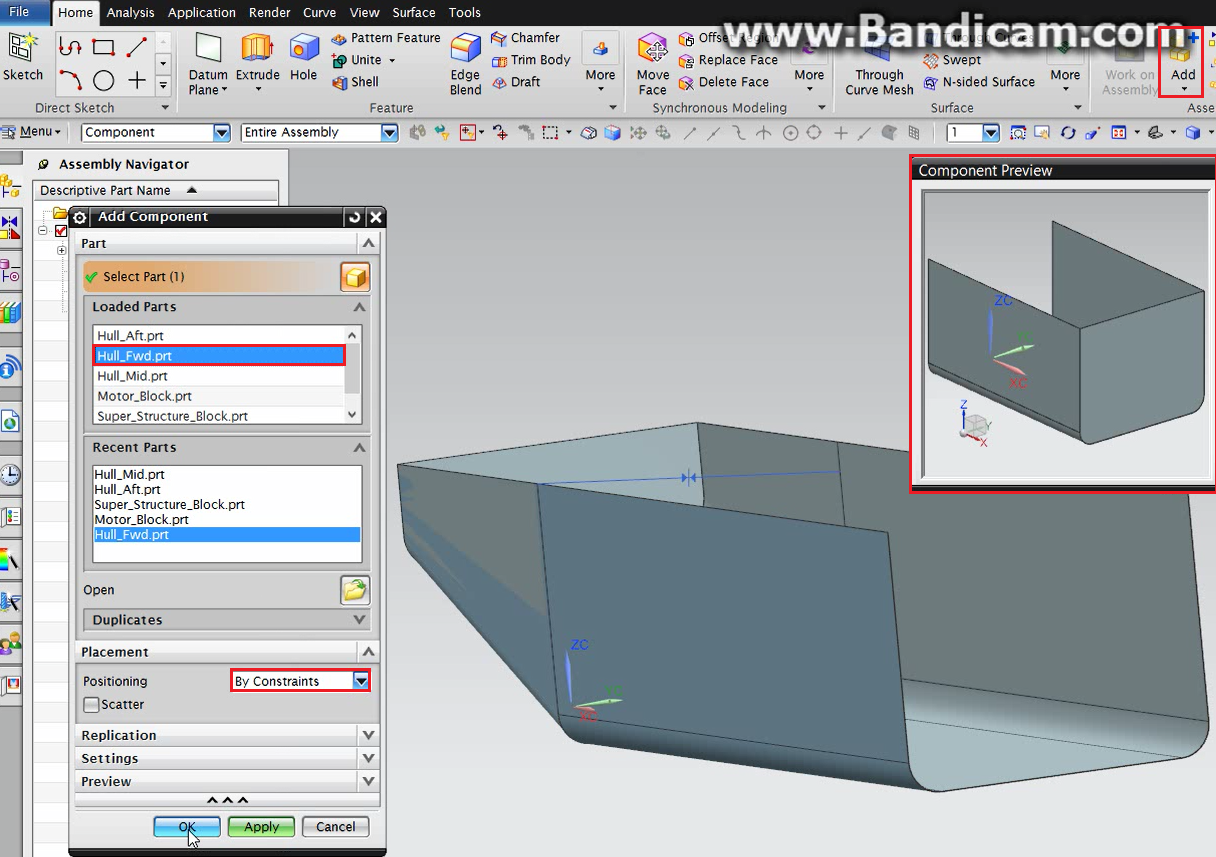
Figure 36 – Bow Section Load
The positioning can be done as it was done between the stern and middle section. The process can be seen at Figure 37. The positioning result can be seen at Figure 38.
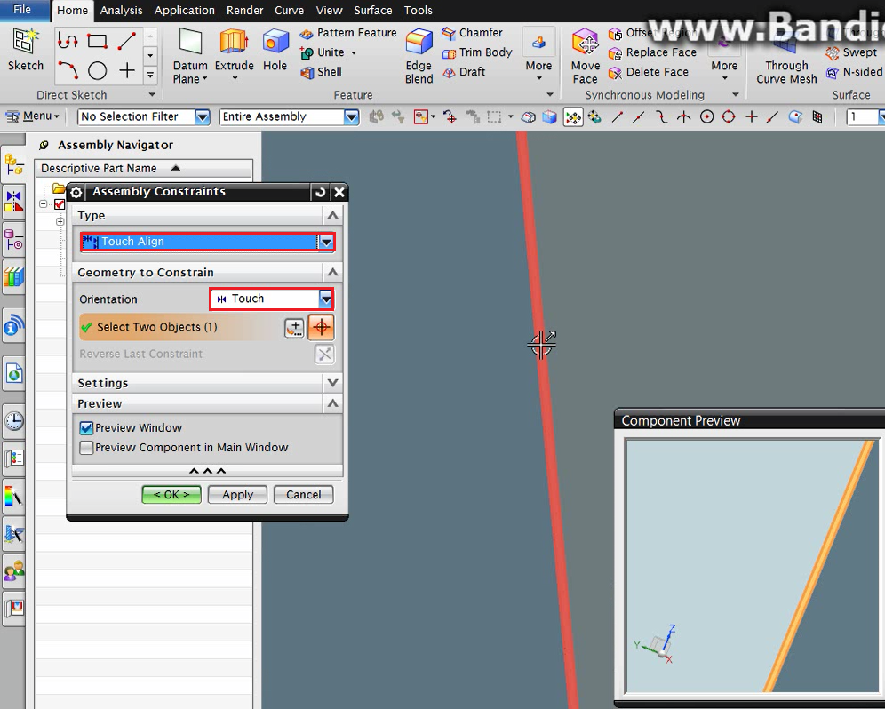
Figure 37 – Bow Section Positioning
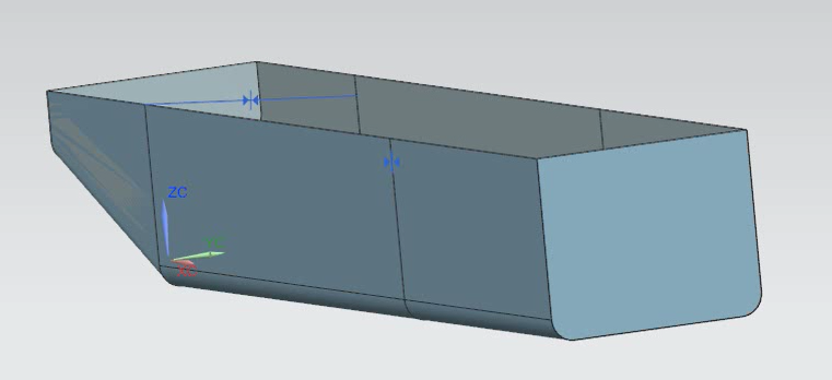
Figure 38 – Stern, Middle and Bow Sections Positioned
The next step is loading the motor block. The placement field should contain the By Constraints method. This will allow the right positioning of the part in relation to the parts previously loaded. The process can be seen at Figure 39.

Figure 39 – Motor Block Load
To be correctly positioned, the motor block will be placed using two constraints. The first constraint type to be applied will be Touch Align. In the orientation field, the Touch option should be selected. The touching faces (Figure 40) should be selected in both of the part, at the component preview window for the motor block and at NX main window for the bow section.
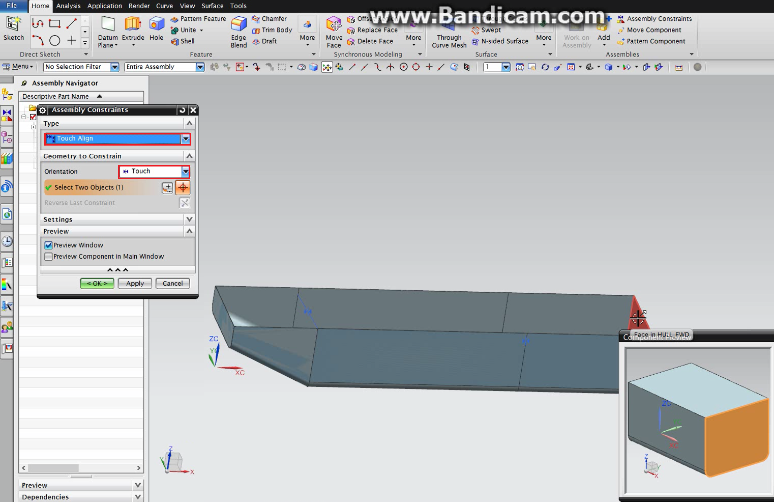
Figure 40 – Motor Block Positioning 1
The second constraint type to be applied will be, also, Touch Align. But, in the orientation field, the Align option should be selected. The faces to be aligned (Figure 41) should be selected in both of the part, at the component preview window for the motor block and at NX main window for the bow section. That way, the top of the motor block will be aligned with the top edge of the bow section. More details about the process can be seen at Figure 41.
Figure 41 – Motor Block Positioning 2
The next step is loading the superstructure block. The placement field should contain the By Constraints method. This will allow the right positioning of the part in relation to the parts previously loaded. The process can be seen at Figure 42.
To be correctly positioned, the superstructure block will be placed using two constraints. The first constraint type to be applied will be Touch Align. In the orientation field, the Align option should be selected. The faces to be aligned (Figure 43) should be selected in both of the part, at the component preview window for the superstructure and at NX main window for the bow section.
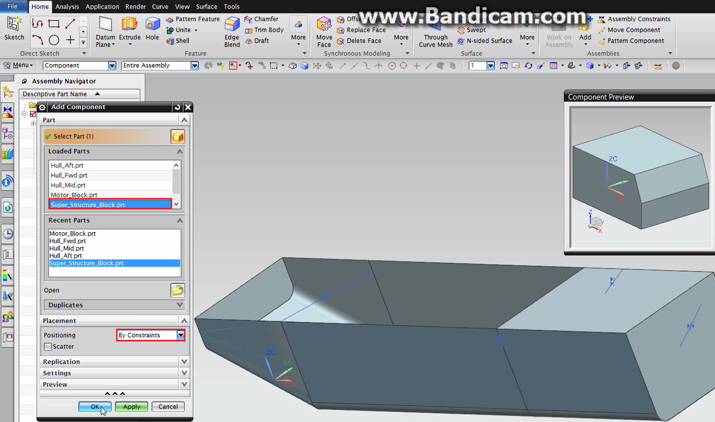
Figure 42 – Superstructure Load
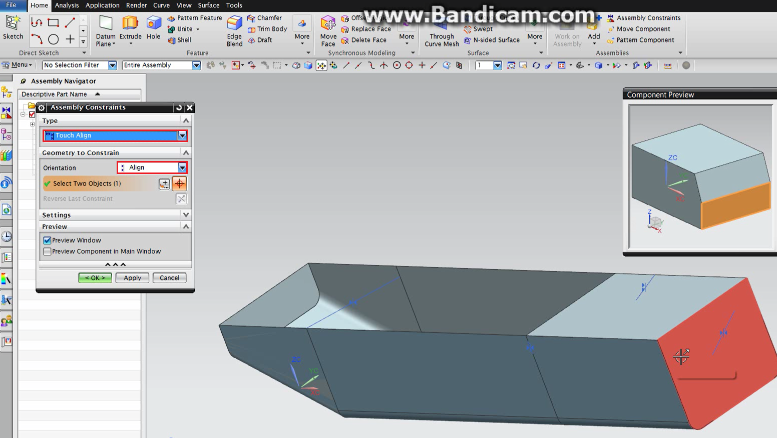
Figure 43 – Superstructure Positioning 1
The second constraint type to be applied will be, also, Touch Align. But, in the orientation field, the Touch option should be selected. The touching faces (Figure 44) should be selected in both of the part, at the component preview window for the superstructure block and at NX main window for the motor block. That way, the top of the motor block will touch the bottom of the superstructure block. More details about the process can be seen at Figure 44.
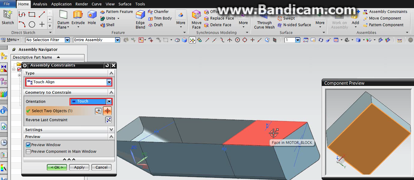
Figure 44 – Superstructure Positioning 2
7 – Final Design
After the assembly is finished, the parametric model is completed. Now, it is possible to play with the main dimensions of the vessel, as it is possible to see at Figure 45. To generate the right model, it was only necessary to open the expression window and change the values of some variables, namely Beam, Lpp and Depth.
It is possible to construct more modules to add to the final design. It is also possible to design, for example, different Bow modules and exchange it according with ship-owner’s requirements. The same is applied to all modules compounding the vessel.
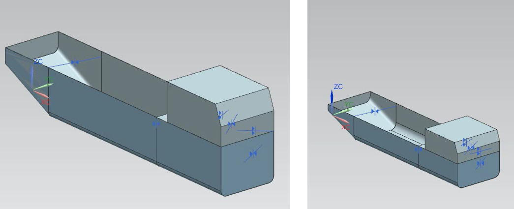
Figure 45 – Change at Parameterized Dimensions