HomeParametric Ship Design – A Simple Application in HTML + Javascript
Parametric Ship Design – A Simple Application in HTML + Javascript
by Henrique M. Gaspar – Associate Professor Aalesund University College / Ulstein International SA
(hega @ hials.no), v0.1, Dec 2013.
Introduction to Parametric Design
The objective of the parametric design procedure is to establish a consistent parametric description of the vessel in the early stages of design, starting from the basic design principle that a certain description of a vessel should be able to perform efficiently a given mission. The scope of the document is to present an entire but simplified iteration of the parametric design process applied to OSVs, starting from the mission parameters until the final design characteristics and attributes.
The procedure presented here encompasses a very simple mission, composed by three operational profiles, each of them connected to an operational state. Another limitation is the absence of a time percentage in each of the operational states, precluding a proper evaluation of the operation revenue, converging to a static assessment of the ship performance.
Methodology
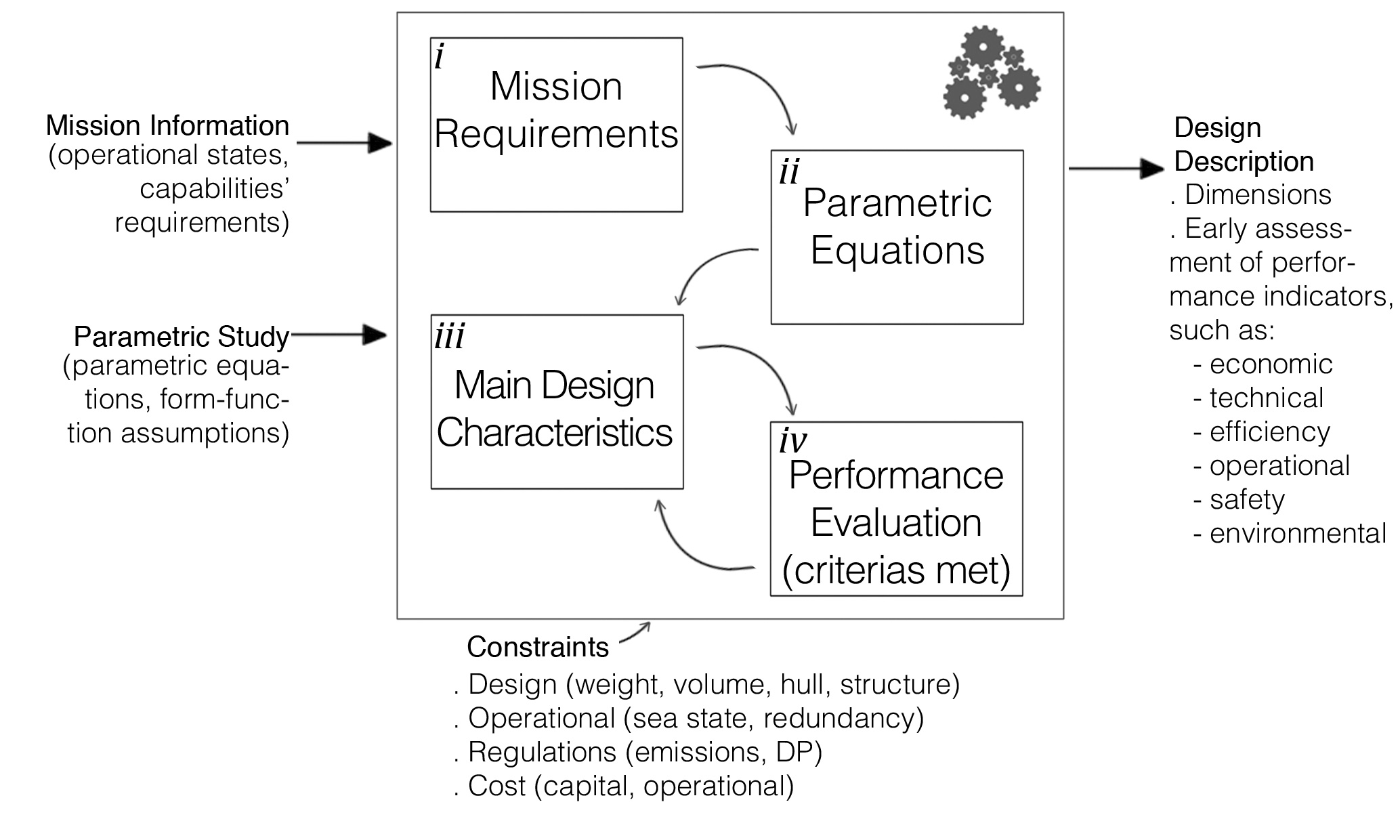
The strategy for the parametric design consists of creating a preliminary methodology containing the aspects necessary to describe a vessel based on its operational requirements. The methodology must be flexible enough to incorporate more advanced methods, inputs and outputs, and for this reason is exemplified in its general terms in Figure 1.
Figure 1 – Parametric Design Methodology
It receives as input information from the mission, with the required operational states, capabilities requirements and other stakeholders’ expectations, as well as the parametric study, with the basis for the parametric equations, design assumptions and other form-function information. Constraints outside the parametric study are also part of the model, consisting of structural and operational limitation, laws and regulations (e.g. from classification societies) and economic.
The general parametric design toolset should consist of four modules: i) mission information translated into requirements, connected to field variables (e.g. depth), vessel capabilities (e.g. cargo capacity) and operational attributes (e.g. powering); ii) Parametric equations are extracted from the parametric study, connecting the mission requirements with expected functionalities of the vessel, as well as these functionalities connected to the vessel main characteristics; iii) Main design characteristics involves main parameters (e.g. LBDT), ratios (e.g. B/L, D/B), coefficients (e.g. CB, CP, CM) and other structural information; iv) Performance evaluation consists of checking if a vessel with the parameters decided in iii complies with the criteria and expectations.
The last part generates a design description, with the main characteristics and attributes, via an early assessment of key performance indicators (KPIs), such as capital cost and price, space allocation, main equipment, weights and centers, basic stability, powering checks and other attributes able to be benchmarked.
Preliminary Parametric Study and Equations
A parametric study is the input to estimate how the use of experienced-based data can be used to obtain main design parameters with ship functionalities and consequently mission requirements. This information usually consists of:
Vessel main characteristics, including deadweight, installed power, number of crew and passenger, major equipment specs (e.g. anchor handling, winches, offshore crane, cargo handling equipment)
Non-dimensional number and other relevant relationships
Tonnages and volumes (e.g. hull and superstructure volumes)
Inspecting general arrangements drawings to estimate deck heights and equipment centers, which will be used for tanks calculation, as well as the measurement of areas for rooms, subsystems and equipment
The preliminary study presented as follows is a very simple case, with fictional data, few parameters and few data points, with the intention of exemplify the first iteration of the method. A proper parametric study should be able to obtain reliable parametric equations, based on careful and coherent statistical analysis. The following data is based on the non-realistic values, and therefore is just presented for illustration purposes.
Parametric Design Example
1 – Mission, Requirements and Capabilities
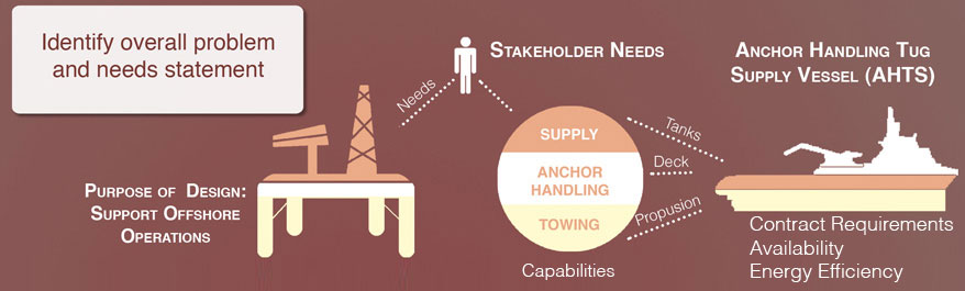
The problem is to design an AHTS for the support of offshore operations. The purpose of the design is narrowed to supply, anchor handling and towing missions. Each mission is considered a set of operational profiles, with minimal requirements related to the task activity, such as: supply capacity (e.g. cargo volume >= 5000m3 and cargo area >= 500m2 ), field operations requirements (e.g. bollard pull (e.g. >= 200ton), illustrated in Figure 2.
Figure 2 – AHTS link between stakeholder’s expectatations and mission performance
An OSV mission is decomposed in three operational profiles: anchor handling, supplging and towing. Each of the operational states’ requirements are connected to three vessel capabilities: cargo deck area [m2], bollard pull [MT] and cargo volume [m3].
Table 1 – Mission, requirements and capabilities
Capability
A. Handling
Supplying
Towing
Total
Cargo deck area [m2]
Bollard pull [MT]
Cargo volume [m3]
The value of the table connects mission requirements with vessel capabilities.By changing any of the values, the total required capability changes, modifying the criteria and the requirement dependency wheel below.
This visualization scheme represents the data from Table 1 via a dependency wheel. On the right side we find the three operational profiles, while on the left side we find the capabilities.
The lenght of the border represents the total values of the capabilities in percentage, normalized to 100%. The thickness of the line connecting capabilities and operational profiles represents a dependency between the two aspects. The length of the circle border of the operational profiles are related to the amount of vessel capabilities required to perform a that task. Dependencies are filtered when passing the mouse over the borders of the circle.
2 – Linking capabilities requirements to vessel parameters via parametric equations
The next step consists of linking the capabilities with the vessel parameters, via the design equations, obtaining a minimum value for the capabilities installed. These values are used later as one of the criteria to evaluate the design.
A set of concepts and assumptions is then defined, for the mapping between the design variables and design behavior. This process includes the knowledge intrinsic to the design process. In this example, only for illustrative purposes, our assumptions will be based under a regression analysis from similar designs. A total value for the requirements is found in Table 2.
Cargo volume: (∝) 0.4 * the cubic number (CN) [m3]
Cargo deck Area: (∝) 0.4 * Total Deck Area [m2]
Powering: (∝) Bollard Pull [ton]
Table 2 – Linking mission requirements with equivalent vessel capability
Max. Capability Requirements
Total Value Re.
Equivalent Capacity Required
Cargo deck area [m2]
LB [m2]
Bollard pull [MT]
Powering [kW]
Cargo volume [m3]
LBD [m3]
The total value required for each capability from Table 1 is connected an equivalent vessel capability. This connection is based on the parametric study and other design information.”
3 – Defining Main Vessel Parameters
The definition of the main vessel parameters is also obtained from the parametric equations. In this example, the hull is defined based on these equations, having the value of length (L) and block coefficient (CB) as user defined. The breadth/length (B/L), depth/breadth (D/B) and draft/depth (T/D) ratios are flexible within the range obtained at the parametric study. For the sake of illustration, an amount of extra powering and price per gross tonnage (kNOK/GT) can also be defined by the designer.
By sliding the bars and modifying the vessel parameters we are able to change its capabilities, and consequently evaluate if the criteria is met.
4 – Criteria
The last step consists of checking the parameters with the criteria defined by the mission, evaluting the design.
Table 4 – Criteria Evaluation
Capabilities
Value
Criteria Met (y/n)
LBD [m3]
LB [m2]
Power [kW]
The criteria is calculated based on the mission requirements. A “Yes” means that the vessel parameters complies with the requirements.”
5 – Output – Design Description
A final design description is obtained at the end of the iterative process.
Table 5 – Design Description
Main Characteristics
Value
Length [m]
Breadth [m]
Depth [m]
Draft [m]
GT
Cb
Displacement [ton]
Attributes
Cargo Volume [m3]
Cargo Area [m2]
Installed Power [kW]
Price [kNOK]
This table summarizes the vessel characteristics and attributes, based on the parameters.
References
Parsons, M. G., Parametric Design, Chapter 11 in Ship Design and Construction vol. 1, SNAME 2004
Erikstad, S. O. and Levander, K., System Based Design of Offshore Support Vessels, in IMDC – Galsgow, UK, 2012
Gaspar, H.M. et al. Handling Temporal Complexity in the Design of Non-Transport Ships Using Epoch-Era Analysis. Transactions RINA, Vol 154, Part A3, International Journal Maritime Engineering, Jul-Sep 2012
Gaspar, H.M. et al., Addressing Complexity Aspects in Conceptual Ship Design – A Systems Engineering Approach. Transactions of SNAME, Vol. 120, 2013
Ulstein, T., and Brett, P. O. Seeing what is next in design solutions: Developing the capability to build a disruptive commercial growth engine in marine design. International Maritime Design Conference – Trondheim (2009).
Ulstein, T., and Brett, P. O. Critical systems thinking in ship design ap- proaches. International Maritime Design Conference – Glasgow (2012).